Wednesday, July 12, 2017

Architectural Pattern

Architectural Pattern

  • As the requirements model is developed, you’ll notice that the software must addressa number of broadproblems that span the entire application. 
  • For example, the requirements model for virtually every e-commerce application is faced with the following problem:
    • How do we offer a broad array of goods to a broad array of customers? 
    • Allow those customers to purchase our goods online?
  • The requirements model also defines a context in which this question must be answered. 
  • For example, an e-commerce business that sells golf equipment to consumers will operate in a different context than an e-commerce business that sells high-priced industrialequipment to medium and large corporations.
  • In addition, a set of limitations and constraints may affect the way in which you addressthe problem to be solved. 
  • Architectural patterns address an application-specific problem within a specific context and under a set of limitations and constraints. 
  • The pattern proposes an architectural solution that can serve as the basis for architectural design…

Tuesday, July 11, 2017

Architectural Styles | Taxonomy of Architectural Styles | Data-Centered Architecture | Data Flow architectures | Call and return architectures | Object-oriented architectures | Layered architectures

Architectural Styles

  • Introduction : 
  • For example (For understanding purpose)
  • When a builder uses the phrase “center hall colonial” to describe a house, most people familiar with houses in a general image of what the house will look like and what the floor plan is likely to be. 
  • The builder has used an architectural style as a descriptive mechanism to differentiate the house from other styles (e.g., A-frame, raised ranch, Cape Cod). 
  • The architectural style is also a template for construction. 
  • Further details of the house must be defined, its final dimensions must be specified, customized features may be added, building materials are to be determined, but the style—a “center hall colonial”—guides the builder in his work. 
  • software architecture represents a structure in which some collection of entities (often called components) is connected by a set of defined relationships (often called connectors). 
  • Both components and connectors are associated with a set of properties that allow the designer to differentiate the types of components and connectors that can be used.
  • Introduction: 
  • The software that is built for computer-based systems also exhibits one of many architectural styles.
  • Each style describes a system category that encompasses 
    • (1) A set of components (e.g., a database, computational modules) that perform a function required by a system; 
    • (2) A set of connectors that enable “communication, coordination and cooperation” among components;
    • (3) Constraints that define how components can be integrated to form the system;
    • (4) Semantic models that enable a designer to understand the overall properties of a system by analyzing the known properties of its constituent parts.

Taxonomy of Architectural Styles

  • Introduction:
  • Millions of computer-based systems have been created over the past 60 years, the vast majority can be categorized into one of a relatively small number of architectural styles 
  • The following are the Taxonomy (Classification) of Architectural Style
    • (1) Data-centered architectures 
    • (2) Data flow architectures 
    • (3) Call and return architectures 
    • (4) Object-oriented architectures
    • (5) Layered architectures

Data-Centered Architecture

Data-Centered Architecture


  • Introduction:
  • A data store (e.g., a file or database) resides at the center of this architecture and is accessed frequently by other components that 
    • update, add, delete, or otherwise modify data within the store. 
  • Figure in slide, illustrates a typical data-centered style. Client software accesses a central repository (Storage area).
  • Data-centered architectures promote inerrability. That is, existing components can be changed and new client components added to the architecture without concern about other clients 
  • (because the client components operate independently). 
  • In addition, data can be passed among clients using the black-board mechanism (i.e., the blackboard component serves to coordinate the transfer of information between clients). 
  • Client components independently execute processes.

Data Flow architectures

  • This architecture is applied when input data are to be transformed through a series of computational or manipulative components into output data. 
  • A pipe-and-filter pattern (in Figure) has a set of components, called filters, connected by pipes that transmit data from one component to the next.
  • Each filter works independently of those components upstream and downstream, is designed to expect data input of a certain form, and produces data output (to the next filter) of a specified form. 
  • However, the filter does not require knowledge of the workings of its neighboring filters. 
  • If the data flow degenerates into a single line of transforms, it is termed batch sequential. This structure accepts a batch of data and then applies a series of sequential components (filters) to transform it
batch sequential

pipes filters

An example of the pipe and filter architecture

An example of the pipe and filter architecture

Call and return architectures

  • This architectural style enables you to achieve a program structure that is relatively easy to modify and scale.
  • A number of substyles exist within this category…
  • Main program/subprogram architectures. This classic program structure decomposes function into a control hierarchy where a “main” program” invokes a number of program components that in turn may invoke still other components. an architecture of this type.
  • Remote procedure call architectures. The components of a main program/subprogram architecture are distributed across multiple computers on a network.
Main program/subprogram architectures

Object-oriented architectures

  • The components of a system encapsulate data and the operations that must be applied to manipulate the data.
  • Communication and coordination between components are accomplished via message passing…

Layered architectures

Layered architectures
  • The basic structure of a layered architecture is illustrated in Figure.
  • A number of different layers are defined, each accomplishing operations that progressively become closer to the machine instruction set.
  • At the outer layer, components service user interface operations.
  • At the inner layer, components perform operating system interfacing.
  • Intermediate layers provide utility services and application software functions…

Monday, July 10, 2017

Architectural design | What is Architecture? | Difference between Architectural & Design

Introduction of Architectural design

  • Architectural design represents
    • The structure of data
    • Program components ,that are required to build a computerbased system.
  • Architectural design considers the architectural style that the system will take, 
    • The structure and properties of the components that constitute the system, 
    • The interrelationships that occur among all architectural components of a system.

What is Architecture?

  • Bass, Clements, and Kazman define this term in the following way:
  • The software architecture of a program or computing system is the structure or structures of the system, which comprise (include) software components, the externally visible properties of those components, and the relationships among them. 
  • For example : It is something like building a home and prepare a model of it. Finally, it is an art. 
  • The architecture is not the operational software. Rather, it is a representation that enables you to 
    • (1) Analyze the effectiveness of the design in meeting its stated requirements, 
    • (2) Consider architectural alternatives at a stage when making design changes is still relatively easy, 
    • (3) Reduce the risks associated with the construction of the software.
  • The definition emphasizes the role of “software components” in any architectural representation. 
  • In the context of architectural design, a software component can be something as simple as a 
    • Program module or an object-oriented class, 
    • Database
    • Middleware
  • The properties of components are those characteristics that are necessary for an understanding of how the components interact with other components. 
  • At the architectural level, internal properties (e.g., details of an algorithm) are not specified. 
  • The relationships between components can be as simple as a procedure call from one module to another or as complex as a database access protocol.

Difference between Architectural & Design

  • Introduction
  • For example (For understanding purpose)
  • When a builder uses the phrase “center hall colonial” to describe a house, most people familiar with houses in a general image of what the house will look like and what the floor plan is likely to be. 
  • The builder has used an architectural style as a descriptive mechanism to differentiate the house from other styles (e.g., A-frame, raised ranch, Cape Cod). 
  • The architectural style is also a template for construction. 
  • Further details of the house must be defined, its final dimensions must be specified, customized features may be added, building materials are to be determined, but the style—a “center hall colonial”—guides the builder in his work. 
  • software architecture represents a structure in which some collection of entities (often called components) is connected by a set of defined relationships (often called connectors). 
  • Both components and connectors are associated with a set of properties that allow the designer to differentiate the types of components and connectors that can be used.

Thursday, July 6, 2017

Design Model | Dimensions of the Design Model | Data Design Elements | Architectural Design Elements | Interface Design Elements | Component-Level Design Elements | Deployment-Level Design Elements

Introduction of Design Model

  • The design model can be viewed in two different dimensions.
    • (Horizontally) The process dimension
      • It indicates the evolution of the parts of the design model as each design task is executed.
    • (Vertically) The abstraction dimension 
      • It  represents the level of detail as each element of the analysis model is transformed into the design model and then iteratively refined. 
  • The elements of the design model use many of the same UML diagrams that were used in the analysis model.
  • The difference is that these diagrams are
    • Refined and elaborated as part of design; 
    • More implementation-specific detail is provided, 
    • Architectural structure and style, components that reside within the architecture, 
    • Interfaces between the components and with the outside world are all emphasized.

Design Model Introduction


Design Model Introduction

Dimensions of the Design Model

Dimensions of the Design Model

Data Design Elements

  • Customer’s/ User’s View:
    • Data Architecting (Creates a model of data that is represented at a high level of abstraction). (Build Architecture of Data) 
  • Program Component Level: The design of Data structure & algorithms. 
  • Application Level: Translate Data Model into a database. 
  • Business Level: Data warehouse(Reporting & Analysis of DB) & Data mining(Analysis). 
  • At last it means creation of Data Dictionary.

Architectural Design Elements

  • Provides an overall view of the software product(Similar like Floor Plan of house) 
  • The architectural model [Sha96] is derived from three sources:
    • (1) Information about the application domain for the software to be built; 
    • (2) Specific requirements model elements such as data flow diagrams or analysis classes, their relationships and collaborations for the problem at hand; 
    • (3) The availability of architectural styles (Chapter 9) and patterns
  • Difference: An architectural style is a conceptual way of how the system will be created / will work. 
  • An architectural pattern describes a solution for implementing a style at the level of subsystems or modules and their relationships.

Interface Design Elements

  • The interface design elements for software represent information flows into and out of the system and how it is communicated among the components defined as part of the architecture. 
  • For example : A set of detailed drawings (and specifications) for the doors, windows, and external utilities of a house. These drawings describe the size and shape of doors and windows, the manner in which they operate, the way in which utility connections (e.g., water, electrical, gas, telephone) come into the house and are distributed among the rooms depicted in the floor plan.
  • There are three important elements of interface design: 
    • (1) The user interface (UI); 
    • (2) External interfaces to other systems, devices, networks, or other producers or consumers of information; 
    • (3) Internal interfaces between various design components. 
  • UI design (increasingly called usability design) is a major software engineering action
  • Usability design incorporates 
    • Visual elements (e.g., layout, color, graphics, interaction mechanisms), 
    • Ergonomic elements (e.g., information layout and placement, metaphors, UI navigation), 
    • Technical elements (e.g., UI patterns, reusable components). 
    • In general, the UI is a unique subsystem within the overall application architecture.
Interface Design Elements


  • The design of external interfaces requires perfect information about the entity to which information is sent or received. 
  • The design of external interfaces should incorporate error checking and (when necessary) appropriate security features 
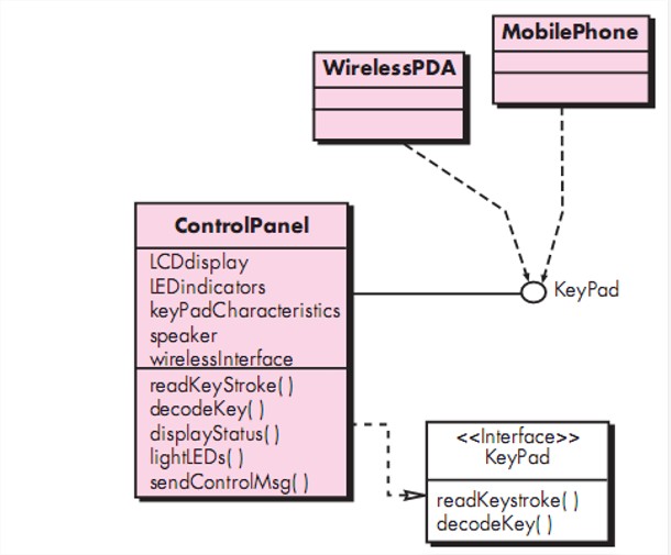
  • For example, the SafeHome security function makes use of a control panel that allows a homeowner to control certain aspects of the security function. 
  • In an advanced version of the system, control panel functions may be implemented via a wireless PDA or mobile phone. 
  • The ControlPanel class (in Figure ) provides the behavior associated with a keypad, and therefore, it must implement the operations readKeyStroke () and decodeKey (). 
  • If these operations are to be provided to other classes (in this case, WirelessPDA and MobilePhone), it is useful to define an interface as shown in the figure. 
  • The interface, named KeyPad, is shown as an <<interface>> stereotype or as a small, labeled circle connected to the class with a line. The interface is defined with no attributes and the set of operations that are necessary to achieve the behavior of a keypad.

Component-Level Design Elements

  • The component-level design for software fully describes the internal detail of each software component. 
  • Component elements (detailed drawing of each room, wiring, place of switches…) 
    • Internal details of each software component
      • Data structures, 
      • algorithmic details, 
      • interface to access component operation (behavior).

Deployment-Level Design Elements


  • Deployment-level design elements indicate how software functionality and subsystems will be allocated within the physical computing environment that will support the software. 
  • For example, the elements of the SafeHome product are configured to operate within three primary computing environments
    • A home-based PC, 
    • The SafeHome control panel, 
    • Server housed at CPI Corp. (providing Internet-based access to the system).
Deployment-Level Design Elements
  • The diagram shown in Figure is in descriptor form. 
  • This means that the deployment diagram shows the computing environment but does not explicitly indicate configuration details. 
  • For example, the “personal computer” is not further identified. It could be a Mac or a Windows-based PC, a Sun workstation, or a Linux-box.
  • These details are provided when the deployment diagram is revisited in instance form during . 
  • Each instance of the deployment (a specific, named hardware configuration) is identified…

Design Concepts | Abstraction | Architecture | Patterns | Separation | Modularity | Information Hiding | Functional Independence | Refinement | Aspects | Refactoring | Object-Oriented Design Concepts | Design Classes | Cohesion | Coupling

Design Concepts

  • Introduction : A set of fundamental software design concepts have developed over the history of software engineering. 
  • Although the degree of interest in each concept has varied over the years, each has stood the test of time. 
  • Each provides the software designer with a foundation from which more sophisticated design methods can be applied. 
  • The following important software design concepts that span both traditional and object-oriented software development. 
    • (1) Abstraction [data, procedure, control]
    • (2) Architecture [The overall structure of the software] 
    • (3) Patterns [conveys the essence” of a proven design solution] 
    • (4) Separation of Concerns [Divide complex problem in small parts] 
    • (5) Modularity [Small Components] 
    • (6) Information Hiding [controlled interfaces] 
    • (7) Functional Independence
    • (8) Refinement
    • (9) Aspects
    • (10) Refactoring
    • (11) Object-Oriented Design Concepts
    • (12) Design Classes

(1) Abstraction  (Concept / Generalization)

  • Introduction : When you consider a modular solution to any problem, many levels of abstraction can be created. 
    • At the highest level of abstraction, a solution is stated in broad terms using the language of the problem environment. 
    • At lower levels of abstraction, a more detailed description of the solution is provided. 
  • Finally, at the lowest level of abstraction, the solution is stated in a manner that can be directly implemented. 
  • As different levels of abstraction are developed, you work to create both 
    • Procedural abstractions 
    • Data abstractions.
  • A procedural abstraction refers to a sequence of instructions that have a specific and limited function. The name of a procedural abstraction implies these functions, but specific details are suppressed.
  • An example of a procedural abstraction would be the word open for a door. Open implies a long sequence of procedural steps (e.g., walk to the door, reach out and grasp knob, turn knob and pull door, step away from moving door, etc.)
Procedural abstractions


  • A data abstraction is a named collection of data that describes a data object. 
  • In the context of the procedural abstraction open, we can define a data abstraction called door. 
  • A set of attributes that describe the door (e.g., door type, swing direction, opening mechanism, weight, dimensions). 
  • It follows that the procedural abstraction open would make use of information contained in the attributes of the data abstraction door.

(2) Architecture
[The overall structure of the software]

  • Software architecture refers to “the overall structure of the software and the ways in which that structure provides conceptual integrity for a system” [Sha95a]
  • Architecture is the structure or organization of program components (modules), the manner in which these components interact, and the structure of data that are used by the components.
  • The following set of properties that should be specified as part of an architectural design.
    • Structural properties.
    • Extra-functional properties
    • Families of related systems
  • Structural properties : This representation defines the components of a system e.g., modules, objects, filters
    • The manner in which those components are packaged and interact with one another.
    • For example, objects are packaged to encapsulate both data and methods.
  • Extra-functional properties : The architectural design description should address the following.
    • How the design architecture achieves requirements for performance, capacity, reliability, security, adaptability, and other system characteristics.
  • Families of related systems : The architectural design should draw upon repeatable patterns that are commonly encountered in the design of families of similar systems.
    • The design should have the ability to reuse architectural building blocks.

(3) Pattern [”conveys the essence (Fundamental nature) ” of a proven design solution]

  • Design pattern describes a design structure that solves a particular design problem within a specific context.
  • The objective of each design pattern is to provide a description that enables a designer to determine 
    • (1) whether the pattern is applicable to the current work,
    • (2) whether the pattern can be reused (hence, saving design time),
    • (3) whether the pattern can serve as a guide for developing a similar, but functionally or structurally different pattern.

(4) Separation of Concerns
[Divide complex problem in small parts]


  • Separation of concerns is a design concept, that suggests any complex problem can be more easily handled if it is subdivided into pieces that can each be solved and/or optimized independently.
  • A concern is a feature or behavior that is specified as part of the requirements model for the software. By separating concerns into smaller, and therefore more manageable pieces, a problem takes less effort and time to solve. 
  • Separation of concern is manifested (Marked / Visible) in other related design concepts: 
    • Modularity,
    • Aspects, 
    • Functional independence, 
    • Refinement.

(5) Modularity
[Divide complex problem in small parts]

  • Modularity is the most common manifestation of separation of concerns. Software is divided into separately named and addressable components, sometimes called modules, that are integrated to satisfy problem requirements. 
  • It has been stated that “modularity is the single attribute of software that allows a program to be intellectually manageable” [Mye78].
  • Monolithic software (i.e., a large program composed of a single module) cannot be easily grasped by a software engineer. 
  • You modularize a design (and the resulting program) so that 
    • Development can be more easily planned; 
    • Software increments can be defined and delivered;
    • Changes can be more easily accommodated;
    • Testing and debugging can be conducted more efficiently, 
    • Long-term maintenance can be conducted without serious side effects
Modularity [Divide complex problem in small parts]

(6) Information Hiding[Controlled interfaces]

  • The concept of modularity leads you to a fundamental question: “How do I decompose a software solution to obtain the best set of modules?”
  • The principle of information hiding [Par72] suggests that modules be “characterized by design decisions that (each) hides from all others.” In other words, modules should be specified and designed so that information (algorithms and data) contained within a module is inaccessible to other modules that have no need for such information. 
  • Hiding implies that effective modularity can be achieved by defining a set of independent modules that communicate with one another only that information necessary to achieve software function.
  • The use of information hiding as a design criterion for modular systems provides the greatest benefits when modifications are required during testing and later during software maintenance. Because most data and procedural detail are hidden from other parts of the software

(7) Functional Independence

  • The concept of functional independence is a direct result of separation of concerns, modularity, and the concepts of abstraction and information hiding.
  • Functional independence is achieved by developing modules with “singleminded” function.
  • Functional independence is a key to good design, and design is the key to software quality. 
  • Independence is assessed using two qualitative criteria which evaluate quality of design : 
    • Cohesion
    • Coupling
Cohesion :

  • Cohesion measures how strongly each of the functions are related within a program module.
  • Well structured classes guide to highly cohesive programs. If a certain class is performing a set of highly related functions, that class is said to be cohesive.
  • On the other hand, if a class is performing a bunch of totally unrelated functionalities that means the class is not cohesive at all.
Coupling: Degree of Dependence among Components
Coupling:

  • Coupling measures how much each of the program modules are dependent on the other program modules.
  • Interactions between two objects occur because there is coupling.
  • Loosely-coupled programs are high in flexibility and extensibility.
  • Strong coupling is never good because one object can be highly dependent on some other object.
Difference of Cohesion - Coupling

Difference of Cohesion - Coupling


(8) Refinement
(Modification / Improvement)

  • Stepwise refinement is a top-down design strategy originally proposed by Niklaus Wirth. 
  • Refinement is actually a process of elaboration. You begin with a statement of function (or description of information) that is defined at a high level of abstraction. That is, the statement describes function or information conceptually but provides no information about the internal workings of the function or the internal structure of the information. 
  • You then elaborate on the original statement, providing more and more detail as each successive refinement (elaboration) occurs.
Refinement (Modification / Improvement), Stepwise Refinement
  • Abstraction and refinement are complementary concepts. 
  • Abstraction enables you to specify procedure and data internally but suppress the need for “outsiders” to have knowledge of low-level details. 
  • Refinement helps you to reveal (disclose) low-level details as design progresses. Both concepts allow you to create a complete design model as the design develops.

(9) Aspects
( Features / phases )

  • A representation of a cross-cutting concern that must be accommodated as refinement and modularization occur.
  • For example : (Module A cross cut Module B means B cannot be satisfied without considering A).

(10)Refactoring
( Features / phases )

  • Refactoring is a reorganization technique that simplifies the design (or code) of a component without changing its function or behavior.
  • Refactoring is the process of changing a software system in such a way that it does not alter the external behavior of the code [design] yet improves its internal structure.
  • When software is refactored, the existing design is examined for redundancy, unused design elements, inefficient or unnecessary algorithms, poorly constructed or inappropriate data structures, or any other design failure that can be corrected to yield a better design.

(11) Object-Oriented Design Concepts 

  • The object-oriented (OO) paradigm is widely used in modern software engineering. 
  • OO design concepts such as classes and objects, inheritance, messages, and polymorphism, among others are the different features of oo paradigm.

(12) Design Class 

  • Refine analysis classes by providing detail needed to implement the classes and implement a software infrastructure the support the business solution 
  • Five types of design classes can be developed to support the design architecture…..
  • User interface classes – abstractions needed for human-computer interaction (HCI) 
  • Business domain classes – refinements of earlier analysis classes 
  • Process classes – implement lower level business abstractions required to fully manage the business domain classes. 
  • Persistent classes – represents data stores that will persist beyond software execution 
  • System classes – implement software management and control functions…

Requirements Modeling for WebApps | Requirements Modeling Input for Web App | The Content Model | Data Tree | The Interaction Model | Sequence Diagram | State Diagram | The Functional Model | Activity Diagram | Navigation Modeling | The Configuration Model

Requirements Modeling for WebApps

  • Introduction : Web developers are often skeptical (doubtful) when the idea of requirements analysis for WebApps is suggested.
  • “After all,” they argue, “the Web development process must be agile, and analysis is time consuming. It’ll slow us down just when we need to be designing and building the WebApp.”.
  • Requirements analysis does take time, but solving the wrong problem takes even more time.
  • How Much Analysis Is Enough?
    • WebApps is emphasized depends on the following factors:
    • Size and complexity of WebApp increment.
    • Number of stakeholders (analysis can help to identify conflicting requirements coming from different sources).
    • Size of the WebApp team.
    • Analysis can help develop a common understanding of the project.

Introduction

  • It is a good idea to analyze the problem before beginning design. 
  • It is not true that all analysis must precede all design.
  • In fact, the design of a specific part of the WebApp only demands an analysis of those requirements that affect only that part of the WebApp.
    • For example from SafeHome, you could validly design the overall website structure (layouts, color schemes, etc.) without having analyzed the functional requirements.
    • You only need to analyze that part of the problem that is relevant to the design work for the increment to be delivered. 

Requirements Modeling Input for Web App

  • An agile version of the generic software process can be applied when WebApps are engineered. 
  • The process incorporates a communication activity that identifies
    • Stakeholders and user categories, 
    • The business context, 
    • Defined informational and applicative goals, 
    • General WebApp requirements, 
    • Usage scenarios— 
  • All above information that becomes input to requirements modeling. 
  • This information is represented in the form of natural language descriptions, rough outlines, sketches, and other informal representations. 
  • Analysis takes this information and then produces more rigorous models as an output. 
  • The requirements model provides a detailed indication of the true structure of the problem and provides insight into the shape of the solution…

Requirements Modeling Output for WebApps


  • Introduction : Requirements analysis provides a disciplined mechanism for representing and evaluating WebApp content and function.
  • Each of these characteristics can be represented as a set of models that allow the WebApp requirements to be analyzed in a structured manner. While the specific models depend largely upon the nature of the WebApp,
  • There are five main classes of models
  • Content Model : The full spectrum of content to be provided by the WebApp is identified, including text, graphics and images, video, and audio data.
    • Data modeling can be used to identify and describe each of the data objects.
  • Interaction Model : Describes the manner in which users interact with the WebApp.
    • Use-cases can be developed to provide detailed descriptions of this interaction.
  • Functional Model : The usage scenarios (use-cases) created as part of interaction analysis define the operations that will be applied to WebApp content and imply other processing functions. All operations and functions are described in detail.
  • Navigation Model : Defines the overall navigation strategy for the webApp.
  • Configuration Analysis. The environment and infrastructure in which the WebApp resides are described in detail.

The Content Model 

  • Content objects are extracted from use-cases
    • examine the scenario description for direct and indirect references to content 
  •  Attributes of each content object are identified 
  • The relationships among content objects and/or the hierarchy of content maintained by a WebApp
    • Relationships—entity-relationship diagram or UML 
    • Hierarchy—data tree or UML

Data Tree

Data Tree

The Interaction Model

  • Composed of four elements: 
    • use-cases 
    • sequence diagrams
    • state diagrams
    • a user interface prototype

Sequence Diagram

Sequence Diagram

State Diagram

State Diagram

The Functional Model

  • The functional model addresses two processing elements of the WebApp
    • user observable functionality that is delivered by the WebApp to end-users 
    • the operations contained within analysis classes that implement behaviors associated with the class. 
  • An activity diagram can be used to represent processing flow

Activity Diagram

Activity Diagram

Navigation Modeling-I 

  • Introduction : Navigation modeling considers how each user category will navigate from one WebApp element (e.g., content category will navigate from one WebApp element (e.g., content object) to another.The mechanics of navigation are defined as part of design. At this stage, you should focus on overall navigation requirements. 
  • The following questions should be considered… 
  • Should certain elements be easier to reach (require fewer navigation steps) than others? What is the priority for presentation?
  • Should certain elements be emphasized to force users to navigate in their direction? 
  • How should navigation errors be handled? 
  • Should navigation be accomplished via links, via search-based access,or by some other means?
  • Should a navigation log be maintained for users?


Navigation Modeling-II 

  • Should a full navigation map or menu (as opposed to a single “back” link or directed pointer) be available at every point in a “back” link or directed pointer) be available at every point in a user’s interaction?
  • For which user category should optimal navigation be designed?
  • How should links external to the WebApp be handled? overlaying the existing browser window? as a new browser window? as a separate frame?

The Configuration Model

  • Server-side
    • Server hardware and operating system environment must be specified
    • Interoperability considerations on the server-side must be considered
    • Appropriate interfaces, communication protocols and related collaborative information must be specified 
  • Client-side
    • Browser configuration issues must be identified
    • Testing requirements should be defined

Tuesday, July 4, 2017

Behavioral Modeling | Identifying Events with the Use Case | State Representations | State diagram | The States of a System | Sequence diagram | Sequence diagram | Points to remember when creating these diagrams

Behavioral Modeling
·         Introduction: Flow Oriented Model represents static elements of the requirements model.
·         It is now time to make a transition to the dynamic behavior of the system or product. To accomplish this, you can represent the behavior of the system as a function of specific events and time.
·         The behavioral model indicates how software will respond to external events.
·         To create the model, the analyst must perform the following steps.
o   Evaluate all use-cases to fully understand the sequence of interaction within the system.
o   Identify events that drive the interaction sequence and understand how these events relate to specific objects.
o   Create a sequencefor each use-case
o   Builda state diagram for the system


o   Reviewthe behavioralmodel to verify accuracy and consistency.


Identifying Events with the Use Case

·         The use case represents a sequence of activities that involves actors and the system.
·         In general, an event occurs whenever the system and an actor exchange information.
·         It has been indicated that an event is not the information that has been exchanged, but rather the fact that information has been exchanged.
·         For example : The use case for a portion of the SafeHome security function.
·         The homeowner uses the keypad to key in a four-digit password. The password is compared with the valid password stored in the system. If the password is incorrect, the control panel will beep once and reset itself for additional input. If the password is correct, the control panel awaits further act.
·         The underlined portions of the use case scenario indicate events. An actor should be identified for each event; the information that is exchanged should be noted,.


·         Here the object, Homeowner, transmits an event to the object ControlPanel. The event might be called password entered.

Identifying Events with the Use Case

State Representations

·         In the context of behavioral modeling, two different characterizations of states must be considered:
o   The state of each class as the system performs its function and
o   The state of the system as observed from the outside as the system performs its function.

·         The state of a class takes on both passive and active characteristics.

o   A passive state is simply the current status of all of an object’s attributes.
o   The active state of an object indicates the current status of the object as it undergoes a continuing processing.

·         For example, the passive state of the class Player (in the video game application) would include the current position and orientation attributes of Player as well as other features of Player that are relevant to the game .

·         The class Player might have the following active states:

o   Moving, at rest, injured, being cured;, lost etc.

·         An event (sometimes called a trigger) must occur to force an object to make a transition from one active state to another.

State diagram


State diagram

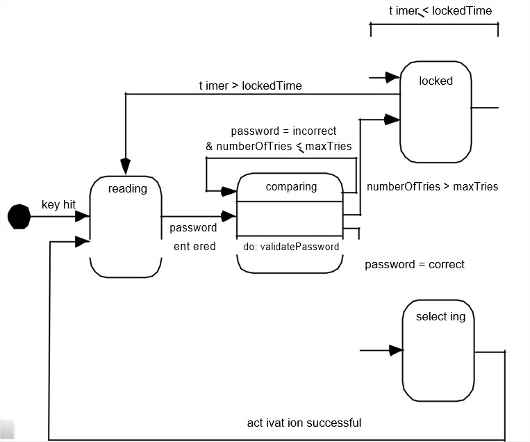
·         One component of a behavioral model is a UML state diagram that represents active states for each class and the events (triggers) that cause changes between these active states.
·         Figure  (In  Previous  Slide)  illustrates  a  state  diagram  for  the ControlPanel object in the Safe Home security function.
·         Each arrow shown in Figure represents a transition from one active state of an object to another. The labels shown for each arrow represent the event that triggers the transition.
·         An action occurs concurrently with the state transition, generally involves one or more operations (responsibilities) of the object.
·         For example, the action connected to the password entered event (ing Figure) is an operation named validatePassword() that accesses a password object and performs a digit-by-digit comparison to validate the entered password.

The States of a System

·         state—a set of observable circum-stances that characterizes the behavior of a system at a given time.
·         state transition—the movement from one state to another.
·         event—an occurrence that causes the system to exhibit some predictable form of behavior.
·         action—process that occurs as a consequence of making a transition.
·         state—a set of observable circum-stances that characterizes the behavior of a system at a given time.
·         state transition—the movement from one state to another.

Sequence diagram

·         The second type of behavioral representation, called a sequence diagram in UML, indicates how events cause transitions from object to object.
·         Once events have been identified by examining a use case, the modeler creates a sequence diagram.
o   It is a representation of how events cause flow from one object to another as a function of time.
o   The sequence diagram is a shorthand version of the use case. It represents key classes and the events that cause behavior to flow from class to class.
·         For example: Figure (In Next Slide) illustrates a partial sequence diagram for the SafeHome security function.
o   Each of the arrows represents an event (derived from a use case)
o   It indicates how the event channels behavior between SafeHome objects.
o   Time is measured vertically (downward),
o   Narrow vertical rectangles represent time spent in processing an activity.
Sequence diagram

Sequence diagram

·         Explanation of Figure: The first event, system ready, is derived from the external environment and channels behavior to the Homeowner object.
·         The homeowner enters a password. A request lookup event is passed to System, which looks up the password in a simple database and returns a result (found or not found) to ControlPanel (now in the comparing state).
A valid password results in a password=correct event to System, which activates Sensors with a request activation event. Ultimately, control is passed back to the homeowner with the activation successful event.

Points to remember when creating these diagrams

State diagram
·         It shows the object undergoing a process.
·         It gives a clear picture of the changes in the object's state in this process.
·         For example ATM withdraw Card
·         object state: Checking, Approving, Rejecting.

·         Sequence diagrams is that,it   is   a good at   showing

sequential logic but not that

good at giving you a "big picture

view “.