Wednesday, November 23, 2016

The Unique Nature of Web Apps

The Unique Nature of Web Apps


Introduction:

In the early days of the World Wide Web (1990 to 1995), websites consisted of little more than a set of linked hypertext files that presented information using text and limited graphics.
Today, WebApps have evolved into sophisticated computing tools that not only provide stand-alone function to the end user, but also have been integrated with corporate databases and business applications due to the development of HTML, JAVA, xml etc.

Attributes of WebApps :

Network Intensiveness
Concurrency
Unpredictable load
Performance
Availability
Data driven
Content Sensitive
Continuous evolution
Immediacy
Security
Aesthetic

Network intensiveness.
A WebApp resides on a network and must serve the needs of a diverse community of clients.
The network may enable worldwide access and communication (i.e., the Internet) or more limited access and communication
(e.g., a corporate Intranet Network Intensiveness)

Concurrency : [ Operation at the same time]
A large number of users may access the WebApp at one time. In many cases, the patterns of usage among end users will vary greatly.

Unpredictable load :
The number of users of the WebApp may vary by orders of magnitude from day to day. One hundred users may show up on Monday; 10,000 may use the system on Thursday.

Performance :
If a WebApp user must wait too long (for access, for server side processing, for client-side formatting and display), he or she may decide to go elsewhere.

Availability :
Although expectation of 100 percent availability is unreasonable, users of popular WebApps often demand access on a 24/7/365 basis.

Data driven :
The primary function of many WebApps is to use hypermedia to present text, graphics, audio, and video content to the end user.
In addition, WebApps are commonly used to access information that exists on databases that are not an integral part of the Web-based environment (e.g., e-commerce or financial applications).

Content sensitive:
The quality and artistic nature of content remains an important
Determinant of the quality of a WebApp.

Continuous evolution:
Unlike conventional application software that evolves over a series of planned, chronologically spaced releases, Web applications evolve continuously.
It is not unusual for some WebApps (specifically, their content) to be updated on a minute-by-minute schedule or for content to be independently computed for each request.

Immediacy:
Although immediacy—the compelling (forceful) need to get software to market quickly—is a characteristic of many application domains,
WebApps often exhibit a time-to-market that can be a matter of a few days or weeks.

Security:
Because WebApps are available via network access, it is difficult, if not impossible, to limit the population of end users who may access the application. In order to protect sensitive content and provide secure mode of data transmission, strong security measures must be implemented.

Aesthetics : [Artistic / Visual]
An undeniable part of the appeal of a WebApp is its look and feel. When an application has been designed to market or sell products or ideas, aesthetic may have as much to do with success as technical design.

Thursday, November 17, 2016

Concurrent Model | Concurrent Engineering

Concurrent Model

Concurrent Model


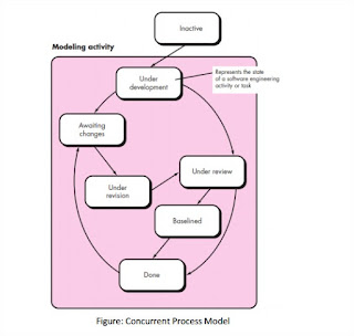
  • The concurrent development model, sometimes called concurrent engineering.

  • It allows a software team to represent iterative and concurrent elements of any of the process model.

  • For example, the modeling activity defined for the spiral model is accomplished by invoking one or more of the software engineering actions: prototyping, analysis, and design.

  • The activity—modeling—may be in any one of the states noted at any given time.

  • Similarly, other activities, actions, or tasks (e.g., communication or construction) can be represented in an similar manner. 
  •     All software engineering activities exist concurrently but reside in         different states.

  • For example, early in a project the communication activity (not shown in the figure) has completed its first iteration and exists in the awaiting changes state.

  • The modeling activity (which existed in the inactive state while initial communication was completed, now makes a transition into the under development state. If, however, the customer indicates that changes in requirements must be made, the modeling activity moves from the under development state into the awaiting changes state. 
  • Concurrent modeling defines a series of events that will trigger transitions from state to state for each of the software engineering activities, actions, or tasks.

Thursday, October 27, 2016

Evolutionary Process Models, stand-alone process model

Evolutionary Process Models, stand-alone process model


Evolutionary models are iterative.
They are characterized develop increasingly more complete versions of the software.

Two common evolutionary process models.
Prototyping.
        The Spiral Model.

Prototyping

Customer defines a set of general objectives for software.

But does not identify detailed requirements for functions and features.

Developer may be unsure of the efficiency of an algorithm.

Prototyping paradigm may offer the best approach.

Can be used as a stand-alone process model.

Better understand what is to be built when requirements are fuzzy.

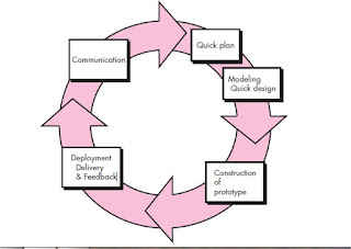
Start with communication, planned quickly, modeling, Construction, Deployment Delivery & Feedback.

Quick design focuses on GUI that visible to end users.

Quick design leads to the construction of a prototype.

Evaluated by stakeholders, who provide feedback that is used to further refine requirements.

Prototype serves as a mechanism for identifying software requirements.

Problems of prototyping

Stakeholders don’t know what appears to be a working version of the software, Unaware, Compromises in implementation working quickly.

Inappropriate operating system or programming language may be used.
Inefficient algorithm may be implemented.

Evolutionary Process Models, stand-alone process model

Incremental Process Models

Incremental Process Models


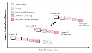
The incremental model combines of linear and parallel process flows.

the incremental model applies linear sequences deliverable “increments” of the software.

first increment is often a core product. That is, basic requirements

The plan addresses the modification of the core product to better meet the needs of the customer and the delivery of additional features and functionality.

process is repeated until the complete product is produced.

focuses on the delivery of an operational product with each increment.

useful when staffing is unavailable for a complete implementation

core product is well received, then additional staff (if required) can be added to implement the next increment.

increments can be planned to manage technical risks.
Incremental Process Models

Wednesday, October 26, 2016

The Waterfall Model, classic life cycle

The Waterfall Model, classic life cycle

When work flows from communication through deployment in a reasonably linear fashion.

It may also occur in a limited number of new development efforts, but only when

requirements are well defined and reasonably stable.

The waterfall model, sometimes called the classic life cycle, suggests a systematic,

sequential approach to software development that begins with customer specification
of requirements and progresses through planning, modeling, construction, and
deployment, culminating in ongoing support of the completed software.


The Waterfall Model, classic life cycle


Problems of Waterfall Model:


1. Real projects rarely follow the sequential flow that the model proposes.

2. difficult for the customer to state all requirements explicitly.
3. customer must have patience.
4. other members of the team to complete dependent tasks.
5. time spent waiting can exceed the time spent on productive work.

A generic process model, iterative process flow, linear process, evolutionary process,parallel process

A generic process model, iterative process flow, linear process, evolutionary process,parallel process


a process was defined as a collection of work activities, actions, and
tasks that are performed when some work product is to be created. Each of these
activities, actions, and tasks reside within a framework or model that defines their
relationship with the process and with one another.
Each software engineering action is defined by a task set that identifies the work
tasks that are to be completed, the work products that will be produced, the quality
assurance points that will be required, and the milestones that will be used to indicate
progress.
defines five framework activities—communication, planning, modeling,
construction, and deployment.

one important aspect of the software process
This aspect—called process flow—describes how the framework
activities and the actions and tasks that occur within each framework
activity are organized with respect to sequence and time.


  • A linear process flow executes each of the five framework activities in sequence, beginning with communication and culminating with deployment.

linear process flow


  • An iterative process flow repeats one or more of the activities before proceeding to the next.

iterative process flow


  • An evolutionary process flow executes the activities in a “circular” manner.

evolutionary process flow


  • A parallel process flow executes one or more activities in parallel with other activities.

parallel process flow


Software characteristics that different from hardware, Software Application Domains

Software characteristics that different from hardware, Software Application Domains

1. Software is developed or engineered; it is not manufactured in the classical sense
2. Software doesn’t "wear out."
3. Although the industry is moving toward component-based construction, most software continues to be custom built.

seven broad categories of computer software

1. System software
2. Application software
3. Engineering/scientific software
4. Embedded software
5. Product-line software
6. Web applications
7. Artificial intelligence software

Saturday, September 3, 2016

Component-Level Design for Traditional Software Component

Component-Level Design for Traditional Software Component


A component is a modular building block for computer software. More formally, the OMG Unified Modeling Language Specification defines a component as “. . . a modular, deployable, and replaceable part of a system that encapsulates implementation and exposes a set of interfaces.”

A traditional component, also called a module, resides within the software architecture.

Three Roles

(1) a control component that coordinates the invocation of all other problem domain components

(2) a problem domain component that implements a complete or partial function that is required by the customer

(3) an infrastructure component that is responsible for functions that support the processing required in the problem domain.

traditional software components are derived from the analysis model.

Control components (modules) reside near the top of the hierarchy, and problem domain components tend to reside toward the bottom of the hierarchy.

A set of data flow diagrams would be derived during requirements modeling. Assume that these are mapped into architecture.

Each box represents a software component. 

Structure chart for a traditional system


The module interface is defined explicitly. That is, each data or control object that flows across the interface is represented.

The data structures that are used internal to the module are defined. The algorithm that allows the module to accomplish its intended function is designed using the step wise refinement approach.
The behavior of the module is sometimes represented using a state diagram.

consider the module ComputePageCost. The intent of this module is to compute the printing cost per page based on specifications provided by the customer. Data required to perform this function are: number of pages in the document, total number of documents to be produced, one- or two-side printing, color requirements, and size requirements.

These data are passed to ComputePageCost via the module’s interface.

Architectural Style and categories of architectural styles

Architectural Style and categories of architectural styles
  • The software that is built for computer-based systems also exhibits one of many architectural styles.
  • Each style describes a system category that encompasses (1) a set of components that perform a function required by a system; (2) a set of connectors that enable “communication, coordination and cooperation” among components; (3) constraints that define how components can be integrated to form the system; and (4) semantic models that enable a designer to understand the overall properties of a system by analyzing the known properties of its constituent parts.
  • An architectural style is a transformation that is imposed on the design of an entire system.
  • The intent is to establish a structure for all components of the system.

the imposition of an architectural style will result in fundamental changes to the structure of the software including a reassignment of the functionality of components.


Categories of Architectural style


·         Data-centered architectures.

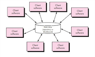
o    A data store resides at the center of this architecture and is accessed frequently by other components that update, add, delete, or otherwise modify data within the store.
o    client software accesses the data independent of any changes to the data or the actions of other client software.
o    A variation on this approach transforms the repository into a “blackboard” that sends notifications to client software when data of interest to the client changes.
Data-centered architectures promote integrability.That is, existing components can be changed and new client components added to the architecture without concern about other clients.
Data-centered architecture

·         Data-flow architectures.
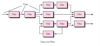
o    This architecture is applied when input data are to be transformed through a series of computational or manipulative components into output data.
o    A pipe-and-filter pattern has a set of components, called filters, connected by pipes that transmit data from one component to the next.
o    Each filter works independently of those components upstream and downstream, is designed to expect data input of a certain form, and produces data output of a specified form.
If the data flow degenerates into a single line of transforms, it is termed batch sequential.
Data-flow architectures
·         Call and return architectures
o   This architectural style enables you to achieve a program structure that is relatively easy to modify and scale.
§  Main program/subprogram architectures.
·         This classic program structure decomposes function into a control hierarchy where a “main” program invokes a number of program components that in turn may invoke still other components.

Main program-subprogram architecture


·         Object-oriented architectures.
o   The components of a system encapsulate data and the operations that must be applied to manipulate the data.
o   Communication and coordination between components are accomplished via message passing.
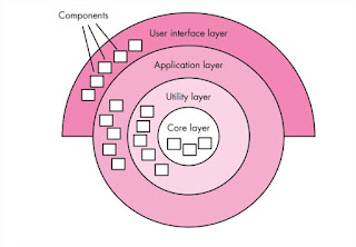
·         Layered architectures.
o   A number of different layers are defined, each accomplishing operations that progressively become closer to the machine instruction set.
o   At the outer layer, components service user interface operations.
o   At the inner layer, components perform operating system interfacing.
o   Intermediate layers provide utility services and application software functions.
Layered architectures

Friday, September 2, 2016

Quality function deployment

Quality function deployment

  • Quality function deployment (QFD) is a quality management technique that translates the needs of the customer into technical requirements for software. 
  • concentrates on maximizing customer satisfaction from the software engineering process. 
  • an understanding of what is valuable to the customer and then deploys these values throughout the engineering process. 
  • Three types of functions:
o   Normal requirements.
§  The objectives and goals that are stated for a product or system during meetings with the customer. If these requirements are present, the customer is satisfied.
§  graphical displays, specific system functions, and defined levels of performance are examples.
o   Expected requirements.
§  These requirements are implicit to the product or system and may be so fundamental that the customer does not explicitly state them. Their absence will be a cause for significant dissatisfaction.
§  ease of human/machine interaction, overall operational correctness and reliability, and ease of software installation are examples.
o   Exciting requirements.
§  These features go beyond the customer’s expectations and prove to be very satisfying when present.
§  For example, software for a new mobile phone comes with standard features, but is coupled with a set of unexpected capabilities (e.g., multitouch screen, visual voice mail) that delight every user of the product.

  • QFD uses customer interviews and observation, surveys, and examination of historical data (e.g., problem reports) as raw data for the requirements gathering activity. 
  • These data are then translated into a table of requirements called the customer voice table.that is reviewed with the customer and other stakeholders. A variety of diagrams, matrices, and evaluation methods are then used to extract expected requirements and to attempt to derive exciting requirements.

Requirements Engineering and Seven distinct tasks

Requirements Engineering and Seven distinct tasks


  • The broad spectrum of tasks and techniques that lead to an understanding of requirements is called requirements engineering. 
  • From a software process perspective, requirements engineering is a major software engineering action that begins during the communication activity and continues into the modeling activity. 
  • It must be adapted to the needs of the process, the project, the product, and the people doing the work. 
  • Requirements engineering builds a bridge to design and construction. 
  • Requirements engineering provides the appropriate mechanism for understanding what the customer wants, analyzing need, ssessing feasibility, negotiating a reasonable solution, specifying the solution unambiguously, validating the specification, and managing the requirements as they are transformed into an operational system. 
  • Seven distinct tasks 
    • inception
    • elicitation
    • elaboration
    • negotiation
    • specification
    • validation, and 
    • management.
  • Some tasks occurs in parallel.

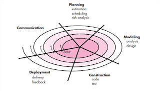
The Spiral Model

The Spiral Model

The Spiral Model

  • Proposed by Barry Boehm.
  • Spiral model is an evolutionary software process model that couples the iterative nature of prototyping with the controlled and systematic aspects of the waterfall model.
  • It provides the potential for rapid development of increasingly more complete versions of the software
  • A risk-driven process model generator that is used to guide multi-stakeholder concurrent engineering of software intensive systems.
  • Two Fetures of spiral model.
  • 1.Cyclic
  • Incrementally growing a system's degree of definition and implementation while decreasing its degree of risk.
  • 2.Anchor Point Milestones
  • Assure that stakeholder commitment to feasible and mutually satisfactory system solutions.
  • divided into a set of framework activities defined by the software engineering team.
  • evolutionary process begins, the software team performs activities that are implied by a circuit around the spiral in a clockwise direction, beginning at the center.
  • Risk is considered as each revolution.
  • A combination of work products and conditions that are attained along the path of the spiral—are noted for each evolutionary pass.
  • Each pass results in adjustments to the project plan.Cost and schedule are adjusted based on feedback derived from the customer.
  • The spiral model is a realistic approach to the development of large-scale systems and software.
  • The spiral model is not a solution.
  • Difficult to convince customers that the evolutionary approach is controllable.
  • If a major risk is not uncovered and managed, problems will undoubtedly occur.