Thursday, July 6, 2017

Requirements Modeling for WebApps | Requirements Modeling Input for Web App | The Content Model | Data Tree | The Interaction Model | Sequence Diagram | State Diagram | The Functional Model | Activity Diagram | Navigation Modeling | The Configuration Model

Requirements Modeling for WebApps

  • Introduction : Web developers are often skeptical (doubtful) when the idea of requirements analysis for WebApps is suggested.
  • “After all,” they argue, “the Web development process must be agile, and analysis is time consuming. It’ll slow us down just when we need to be designing and building the WebApp.”.
  • Requirements analysis does take time, but solving the wrong problem takes even more time.
  • How Much Analysis Is Enough?
    • WebApps is emphasized depends on the following factors:
    • Size and complexity of WebApp increment.
    • Number of stakeholders (analysis can help to identify conflicting requirements coming from different sources).
    • Size of the WebApp team.
    • Analysis can help develop a common understanding of the project.

Introduction

  • It is a good idea to analyze the problem before beginning design. 
  • It is not true that all analysis must precede all design.
  • In fact, the design of a specific part of the WebApp only demands an analysis of those requirements that affect only that part of the WebApp.
    • For example from SafeHome, you could validly design the overall website structure (layouts, color schemes, etc.) without having analyzed the functional requirements.
    • You only need to analyze that part of the problem that is relevant to the design work for the increment to be delivered. 

Requirements Modeling Input for Web App

  • An agile version of the generic software process can be applied when WebApps are engineered. 
  • The process incorporates a communication activity that identifies
    • Stakeholders and user categories, 
    • The business context, 
    • Defined informational and applicative goals, 
    • General WebApp requirements, 
    • Usage scenarios— 
  • All above information that becomes input to requirements modeling. 
  • This information is represented in the form of natural language descriptions, rough outlines, sketches, and other informal representations. 
  • Analysis takes this information and then produces more rigorous models as an output. 
  • The requirements model provides a detailed indication of the true structure of the problem and provides insight into the shape of the solution…

Requirements Modeling Output for WebApps


  • Introduction : Requirements analysis provides a disciplined mechanism for representing and evaluating WebApp content and function.
  • Each of these characteristics can be represented as a set of models that allow the WebApp requirements to be analyzed in a structured manner. While the specific models depend largely upon the nature of the WebApp,
  • There are five main classes of models
  • Content Model : The full spectrum of content to be provided by the WebApp is identified, including text, graphics and images, video, and audio data.
    • Data modeling can be used to identify and describe each of the data objects.
  • Interaction Model : Describes the manner in which users interact with the WebApp.
    • Use-cases can be developed to provide detailed descriptions of this interaction.
  • Functional Model : The usage scenarios (use-cases) created as part of interaction analysis define the operations that will be applied to WebApp content and imply other processing functions. All operations and functions are described in detail.
  • Navigation Model : Defines the overall navigation strategy for the webApp.
  • Configuration Analysis. The environment and infrastructure in which the WebApp resides are described in detail.

The Content Model 

  • Content objects are extracted from use-cases
    • examine the scenario description for direct and indirect references to content 
  •  Attributes of each content object are identified 
  • The relationships among content objects and/or the hierarchy of content maintained by a WebApp
    • Relationships—entity-relationship diagram or UML 
    • Hierarchy—data tree or UML

Data Tree

Data Tree

The Interaction Model

  • Composed of four elements: 
    • use-cases 
    • sequence diagrams
    • state diagrams
    • a user interface prototype

Sequence Diagram

Sequence Diagram

State Diagram

State Diagram

The Functional Model

  • The functional model addresses two processing elements of the WebApp
    • user observable functionality that is delivered by the WebApp to end-users 
    • the operations contained within analysis classes that implement behaviors associated with the class. 
  • An activity diagram can be used to represent processing flow

Activity Diagram

Activity Diagram

Navigation Modeling-I 

  • Introduction : Navigation modeling considers how each user category will navigate from one WebApp element (e.g., content category will navigate from one WebApp element (e.g., content object) to another.The mechanics of navigation are defined as part of design. At this stage, you should focus on overall navigation requirements. 
  • The following questions should be considered… 
  • Should certain elements be easier to reach (require fewer navigation steps) than others? What is the priority for presentation?
  • Should certain elements be emphasized to force users to navigate in their direction? 
  • How should navigation errors be handled? 
  • Should navigation be accomplished via links, via search-based access,or by some other means?
  • Should a navigation log be maintained for users?


Navigation Modeling-II 

  • Should a full navigation map or menu (as opposed to a single “back” link or directed pointer) be available at every point in a “back” link or directed pointer) be available at every point in a user’s interaction?
  • For which user category should optimal navigation be designed?
  • How should links external to the WebApp be handled? overlaying the existing browser window? as a new browser window? as a separate frame?

The Configuration Model

  • Server-side
    • Server hardware and operating system environment must be specified
    • Interoperability considerations on the server-side must be considered
    • Appropriate interfaces, communication protocols and related collaborative information must be specified 
  • Client-side
    • Browser configuration issues must be identified
    • Testing requirements should be defined

Tuesday, July 4, 2017

Behavioral Modeling | Identifying Events with the Use Case | State Representations | State diagram | The States of a System | Sequence diagram | Sequence diagram | Points to remember when creating these diagrams

Behavioral Modeling
·         Introduction: Flow Oriented Model represents static elements of the requirements model.
·         It is now time to make a transition to the dynamic behavior of the system or product. To accomplish this, you can represent the behavior of the system as a function of specific events and time.
·         The behavioral model indicates how software will respond to external events.
·         To create the model, the analyst must perform the following steps.
o   Evaluate all use-cases to fully understand the sequence of interaction within the system.
o   Identify events that drive the interaction sequence and understand how these events relate to specific objects.
o   Create a sequencefor each use-case
o   Builda state diagram for the system


o   Reviewthe behavioralmodel to verify accuracy and consistency.


Identifying Events with the Use Case

·         The use case represents a sequence of activities that involves actors and the system.
·         In general, an event occurs whenever the system and an actor exchange information.
·         It has been indicated that an event is not the information that has been exchanged, but rather the fact that information has been exchanged.
·         For example : The use case for a portion of the SafeHome security function.
·         The homeowner uses the keypad to key in a four-digit password. The password is compared with the valid password stored in the system. If the password is incorrect, the control panel will beep once and reset itself for additional input. If the password is correct, the control panel awaits further act.
·         The underlined portions of the use case scenario indicate events. An actor should be identified for each event; the information that is exchanged should be noted,.


·         Here the object, Homeowner, transmits an event to the object ControlPanel. The event might be called password entered.

Identifying Events with the Use Case

State Representations

·         In the context of behavioral modeling, two different characterizations of states must be considered:
o   The state of each class as the system performs its function and
o   The state of the system as observed from the outside as the system performs its function.

·         The state of a class takes on both passive and active characteristics.

o   A passive state is simply the current status of all of an object’s attributes.
o   The active state of an object indicates the current status of the object as it undergoes a continuing processing.

·         For example, the passive state of the class Player (in the video game application) would include the current position and orientation attributes of Player as well as other features of Player that are relevant to the game .

·         The class Player might have the following active states:

o   Moving, at rest, injured, being cured;, lost etc.

·         An event (sometimes called a trigger) must occur to force an object to make a transition from one active state to another.

State diagram


State diagram

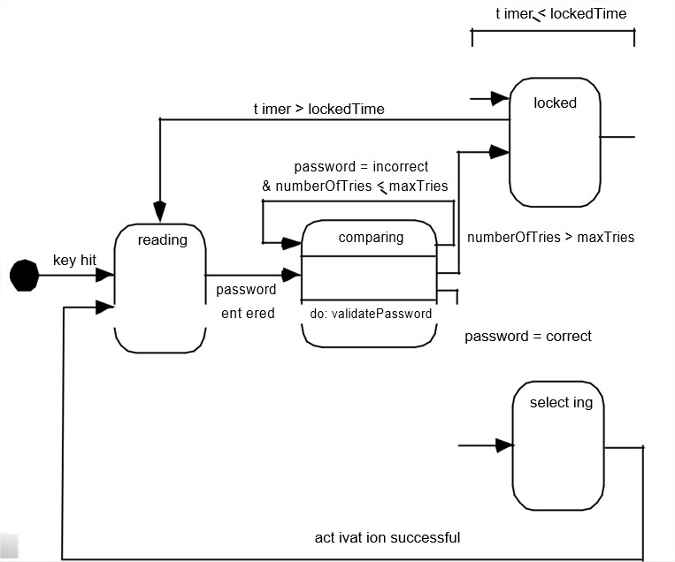
·         One component of a behavioral model is a UML state diagram that represents active states for each class and the events (triggers) that cause changes between these active states.
·         Figure  (In  Previous  Slide)  illustrates  a  state  diagram  for  the ControlPanel object in the Safe Home security function.
·         Each arrow shown in Figure represents a transition from one active state of an object to another. The labels shown for each arrow represent the event that triggers the transition.
·         An action occurs concurrently with the state transition, generally involves one or more operations (responsibilities) of the object.
·         For example, the action connected to the password entered event (ing Figure) is an operation named validatePassword() that accesses a password object and performs a digit-by-digit comparison to validate the entered password.

The States of a System

·         state—a set of observable circum-stances that characterizes the behavior of a system at a given time.
·         state transition—the movement from one state to another.
·         event—an occurrence that causes the system to exhibit some predictable form of behavior.
·         action—process that occurs as a consequence of making a transition.
·         state—a set of observable circum-stances that characterizes the behavior of a system at a given time.
·         state transition—the movement from one state to another.

Sequence diagram

·         The second type of behavioral representation, called a sequence diagram in UML, indicates how events cause transitions from object to object.
·         Once events have been identified by examining a use case, the modeler creates a sequence diagram.
o   It is a representation of how events cause flow from one object to another as a function of time.
o   The sequence diagram is a shorthand version of the use case. It represents key classes and the events that cause behavior to flow from class to class.
·         For example: Figure (In Next Slide) illustrates a partial sequence diagram for the SafeHome security function.
o   Each of the arrows represents an event (derived from a use case)
o   It indicates how the event channels behavior between SafeHome objects.
o   Time is measured vertically (downward),
o   Narrow vertical rectangles represent time spent in processing an activity.
Sequence diagram

Sequence diagram

·         Explanation of Figure: The first event, system ready, is derived from the external environment and channels behavior to the Homeowner object.
·         The homeowner enters a password. A request lookup event is passed to System, which looks up the password in a simple database and returns a result (found or not found) to ControlPanel (now in the comparing state).
A valid password results in a password=correct event to System, which activates Sensors with a request activation event. Ultimately, control is passed back to the homeowner with the activation successful event.

Points to remember when creating these diagrams

State diagram
·         It shows the object undergoing a process.
·         It gives a clear picture of the changes in the object's state in this process.
·         For example ATM withdraw Card
·         object state: Checking, Approving, Rejecting.

·         Sequence diagrams is that,it   is   a good at   showing

sequential logic but not that

good at giving you a "big picture

view “.


Saturday, January 28, 2017

Flow-Oriented Modeling | Data Flow Model | Control Flow Model | Control Specification | Process Specification

Flow-Oriented Modeling | Data Flow Model | Control Flow Model | Control Specification | Process Specification

Although data flow-oriented modeling is perceived as an outdated technique by some software engineers, it continues to be one of the most widely used requirements analysis notations in use today. 

Although the data flow diagram (DFD) and related diagrams and information are not a formal part of UML, they can be used to complement UML diagrams and provide additional insight into system requirements and flow.


The DFD takes an input-process-output view of a system. That is, data objects flow into the software, are transformed by processing elements, and resultant data objects flow out of the software.


Data objects are represented by labeled arrows, and transformations are represented by circles (also called bubbles).  


The DFD is presented in a hierarchical fashion.

That is, the first data flow model (sometimes called a level 0 DFD or context diagram) represents the system as a whole.

Subsequent data flow diagrams refine the context diagram, providing increasing detail with each subsequent level.


Creating a Data Flow Model

Flow-Oriented Modeling | Data Flow Model | Control Flow Model | Control Specification | Process Specification

The data flow diagram enables you to develop models of the information domain and functional domain.

 As the DFD is refined into greater levels of detail, you perform an implicit functional decomposition of the system.

Simple guidelines  the derivation of a data flow diagram:-

(1) the level 0 data flow diagram should depict the software/system as a single bubble.
(2) primary input and output should be carefully noted.
(3) refinement should begin by isolating candidate processes, data objects, and data stores to be represented at the next level.
(4) all arrows and bubbles should be labeled with meaningful names.
(5) information flow continuity must be maintained from level to level.
(6) one bubble at a time should be refined. There is a natural tendency to overcomplicate the data flow diagram.

The refinement of DFDs continues until each bubble performs a simple function.

That is, until the process represented by the bubble performs a function that would be easily implemented as a program component. called cohesion.

Control Flow Model

For some types of applications, the data model and the data flow diagram are all that is necessary to obtain meaningful insight into software requirements.

Such applications require the use of control flow modeling in addition to data flow modeling.

I have already noted that an event or control item is implemented as a Boolean value.

The following guidelines are for select potential candidate events:

·   List all sensors that are “read” by the software.
·   List all interrupt conditions.
·   List all “switches” that are actuated by an operator. 
·   List all data conditions.
·  Recalling the noun/verb parse that was applied to the processing narrative,     review all “control items” as possible control specification inputs/outputs.
·   Describe the behavior of a system by identifying its states, identify how each state is reached, and define the transitions between states.
·  Focus on possible omissions—a very common error in specifying control; for example, ask: “Is there any other way I can get to this state or exit from it?”

The Control Specification

A control specification (CSPEC) represents the behavior of the system in two different ways.

The CSPEC contains a state diagram that is a sequential specification of behavior. It can also contain a program activation table a combinatorial specification of behavior.

A somewhat different mode of behavioral representation is the process activation table. The PAT represents information contained in the state diagram in the context of processes, not states.

That is, the table indicates which processes (bubbles) in the flow model will be invoked when an event occurs.

The PAT can be used as a guide for a designer who must build an executive that controls the processes represented at this level.

The CSPEC describes the behavior of the system, but it gives us no information about the inner working of the processes that are activated as a result of this behavior.

The Process Specification

The process specification (PSPEC) is used to describe all flow model processes that appear at the final level of refinement.

The content of the process specification can include narrative text, a program design language (PDL) description of the process algorithm, mathematical equations, tables, or UML activity diagrams.

By providing a PSPEC to accompany each bubble in the flow model, you can create a “mini-spec” that serves as a guide for design of the software component that will implement the bubble. 

Monday, January 9, 2017

Requirements Modeling Strategies | Structured Analysis | Object-Oriented Analysis

Requirements Modeling Strategies | Structured Analysis

One view of requirements modeling, called structured analysis, considers data and the processes that transform the data as separate entities.

Data objects are modeled in a way that defines their attributes and relationships.

Processes that manipulate data objects are modeled in a manner that shows how they transform data as data objects flow through the system.

A second approach to analysis modeled, called object-oriented analysis, focuses on the definition of classes and the manner in which they collaborate with one another to effect customer requirements.

The question is not which is best, but rather, what combination of representations will provide stakeholders with the best model of software requirements and the most effective bridge to software design.

Validating Requirements | When I review requirements, what questions should I ask?

Validating Requirements | When I review requirements, what questions should I ask?

As each element of the requirements model is created, it is examined for inconsistency, omissions, and ambiguity.

The requirements represented by the model are prioritized by the stakeholders and grouped within requirements packages that will be implemented as software increments.

Following questions:

Is each requirement consistent with the overall objectives for the system/product?

Have all requirements been specified at the proper level of abstraction? That is, do some requirements provide a level of technical detail that is inappropriate at this stage?

Is the requirement really necessary or does it represent an add-on feature that may not be essential to the objective of the system?

Is each requirement bounded and unambiguous?

Does each requirement have attribution? That is, is a source (generally, a specific individual) noted for each requirement?

Do any requirements conflict with other requirements?

Is each requirement achievable in the technical environment that will house the system or product?

Is each requirement testable, once implemented?

Does the requirements model properly reflect the information, function, and behavior of the system to be built?

Has the requirements model been “partitioned” in a way that exposes progressively more detailed information about the system?

• Have requirements patterns been used to simplify the requirements model? Have all patterns been properly validated? Are all patterns consistent with customer requirements?

Wednesday, November 23, 2016

The Unique Nature of Web Apps

The Unique Nature of Web Apps


Introduction:

In the early days of the World Wide Web (1990 to 1995), websites consisted of little more than a set of linked hypertext files that presented information using text and limited graphics.
Today, WebApps have evolved into sophisticated computing tools that not only provide stand-alone function to the end user, but also have been integrated with corporate databases and business applications due to the development of HTML, JAVA, xml etc.

Attributes of WebApps :

Network Intensiveness
Concurrency
Unpredictable load
Performance
Availability
Data driven
Content Sensitive
Continuous evolution
Immediacy
Security
Aesthetic

Network intensiveness.
A WebApp resides on a network and must serve the needs of a diverse community of clients.
The network may enable worldwide access and communication (i.e., the Internet) or more limited access and communication
(e.g., a corporate Intranet Network Intensiveness)

Concurrency : [ Operation at the same time]
A large number of users may access the WebApp at one time. In many cases, the patterns of usage among end users will vary greatly.

Unpredictable load :
The number of users of the WebApp may vary by orders of magnitude from day to day. One hundred users may show up on Monday; 10,000 may use the system on Thursday.

Performance :
If a WebApp user must wait too long (for access, for server side processing, for client-side formatting and display), he or she may decide to go elsewhere.

Availability :
Although expectation of 100 percent availability is unreasonable, users of popular WebApps often demand access on a 24/7/365 basis.

Data driven :
The primary function of many WebApps is to use hypermedia to present text, graphics, audio, and video content to the end user.
In addition, WebApps are commonly used to access information that exists on databases that are not an integral part of the Web-based environment (e.g., e-commerce or financial applications).

Content sensitive:
The quality and artistic nature of content remains an important
Determinant of the quality of a WebApp.

Continuous evolution:
Unlike conventional application software that evolves over a series of planned, chronologically spaced releases, Web applications evolve continuously.
It is not unusual for some WebApps (specifically, their content) to be updated on a minute-by-minute schedule or for content to be independently computed for each request.

Immediacy:
Although immediacy—the compelling (forceful) need to get software to market quickly—is a characteristic of many application domains,
WebApps often exhibit a time-to-market that can be a matter of a few days or weeks.

Security:
Because WebApps are available via network access, it is difficult, if not impossible, to limit the population of end users who may access the application. In order to protect sensitive content and provide secure mode of data transmission, strong security measures must be implemented.

Aesthetics : [Artistic / Visual]
An undeniable part of the appeal of a WebApp is its look and feel. When an application has been designed to market or sell products or ideas, aesthetic may have as much to do with success as technical design.


Thursday, November 17, 2016

Concurrent Model | Concurrent Engineering

Concurrent Model

Concurrent Model


  • The concurrent development model, sometimes called concurrent engineering.

  • It allows a software team to represent iterative and concurrent elements of any of the process model.

  • For example, the modeling activity defined for the spiral model is accomplished by invoking one or more of the software engineering actions: prototyping, analysis, and design.

  • The activity—modeling—may be in any one of the states noted at any given time.

  • Similarly, other activities, actions, or tasks (e.g., communication or construction) can be represented in an similar manner. 
  •     All software engineering activities exist concurrently but reside in         different states.

  • For example, early in a project the communication activity (not shown in the figure) has completed its first iteration and exists in the awaiting changes state.

  • The modeling activity (which existed in the inactive state while initial communication was completed, now makes a transition into the under development state. If, however, the customer indicates that changes in requirements must be made, the modeling activity moves from the under development state into the awaiting changes state. 
  • Concurrent modeling defines a series of events that will trigger transitions from state to state for each of the software engineering activities, actions, or tasks.